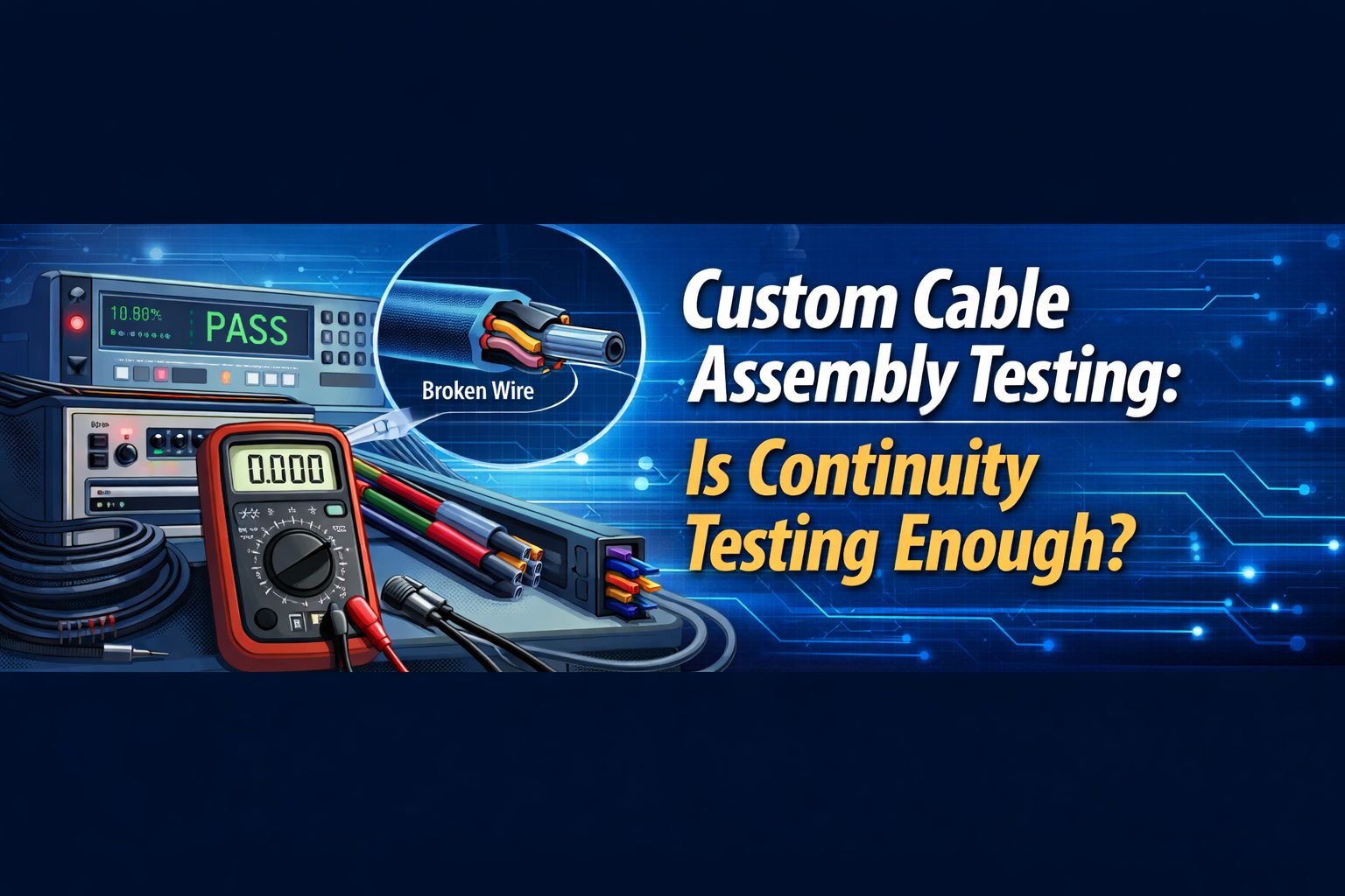
Custom cable assemblies are essential components in modern electronic and electrical systems. From automotive electronics and industrial machinery to telecommunications infrastructure and data centers, reliable cable connections ensure that power and signals are transmitted safely and efficiently.
To guarantee performance and safety, cable assemblies must undergo thorough electrical testing during manufacturing and quality control. One of the most common and fundamental tests is continuity testing, which verifies whether electrical current can flow through the cable without interruption.
While continuity testing is fast, inexpensive, and widely used, it may not always be sufficient—especially for complex or high-reliability cable assemblies. In many cases, additional electrical tests are necessary to ensure insulation integrity, shielding effectiveness, and long-term performance.
This article explains how continuity testing works, why it is important, and what additional testing methods manufacturers use to ensure the quality of custom cable assemblies.
Understanding Continuity Testing in Cable Assemblies
What Is Electrical Continuity?
Electrical continuity refers to the presence of a complete and uninterrupted path that allows electrical current to flow through a circuit. In the context of a cable assembly, continuity ensures that electrical signals or power can travel from one end of the cable to the other without obstruction.
If continuity is lost, the circuit becomes open, meaning electrical current cannot pass through the system. This can lead to equipment malfunction, perda de sinal, or even complete system failure.
Ensuring electrical continuity is therefore one of the first and most important steps in verifying the basic functionality of any cable assembly.
How Continuity Testing Works
Continuity testing typically involves applying a small electrical current through the conductors in the cable assembly. The testing device then checks whether the current successfully flows through the entire circuit.
If the circuit is complete, the device will indicate a closed circuit through an audible signal, visual indicator, or digital reading. If the current cannot pass through the circuit, the device identifies an open circuit, signaling a potential problem in the cable.
Because this test is simple and efficient, it is widely used during manufacturing, troubleshooting, and maintenance processes.
Why Continuity Testing Is Important
Continuity testing plays a critical role in cable assembly quality control for several reasons:
- It quickly verifies that electrical paths are properly connected
- It identifies basic wiring or assembly errors
- It helps prevent faulty cables from entering production systems
- It provides a fast and cost-effective method of initial inspection
Although it does not provide a full performance evaluation, continuity testing ensures that the cable assembly meets basic operational requirements before further testing or installation.
Key Purposes of Continuity Testing for Cable Assemblies
Detecting Open Circuits
One of the primary objectives of continuity testing is to detect open circuits, which occur when the electrical pathway is broken.
Open circuits can be caused by several factors, incluindo:
- Broken or damaged wires
- Poor crimping or soldering connections
- Faulty connectors
- Incorrect cable assembly procedures
When a cable assembly contains an open circuit, electrical current cannot reach the intended endpoint, preventing the connected device from operating correctly.
By identifying these problems early, manufacturers can correct defects before the product reaches the customer.
Verifying Correct Pin-Out
Another key function of continuity testing is verifying the pin-out configuration of multiconductor cables.
Pin-out refers to how each conductor inside the cable connects to specific pins or terminals in a connector. Each wire must be connected to the correct location to ensure proper signal transmission.
Continuity testing helps identify:
- Miswired connections
- Crossed wires
- Incorrect terminal assignments
Incorrect pin-out can cause communication errors, equipment damage, or complete system malfunction. Verifying pin-out ensures that the cable assembly operates exactly as designed.
Ensuring Proper Circuit Completion
Continuity testing confirms that the cable assembly forms a closed circuit between its connection points. This ensures that electrical power or signals can travel reliably from the source to the destination without interruption.
Without proper circuit completion, even a perfectly designed system will fail to operate correctly.
Common Equipment Used for Continuity Testing
Digital Multimeters
Digital multimeters are among the most widely used tools for electrical testing. These devices can measure voltage, atual, resistência, and continuity.
When set to continuity mode, the multimeter sends a small electrical current through the circuit. If the circuit is complete, the device typically produces a beep or visual indication.
Digital multimeters are popular because they are:
- Easy to operate
- Portable and affordable
- Suitable for basic cable testing and troubleshooting
Ohmmeters
An ohmmeter measures electrical resistance between two points in a circuit. Because resistance increases when a conductor is damaged or disconnected, this measurement helps identify faulty wiring.
By evaluating resistance levels, technicians can determine whether a cable path is functioning correctly.
Ohmmeters are especially useful when technicians need more precise resistance measurements beyond simple continuity detection.
Custom Testing Fixtures
In cable manufacturing environments, companies often use custom test fixtures designed specifically for their cable assemblies.
These fixtures may include:
- Dedicated connectors matching the cable design
- LED indicators or buzzers to signal continuity
- Test leads connected to automated testing equipment
Custom fixtures improve testing speed and accuracy, particularly in high-volume production environments.
Challenges and Limitations of Continuity Testing
Intermittent Electrical Connections
Some electrical faults occur intermittently rather than continuously. These intermittent connections can be particularly difficult to detect.
Common causes include:
- Connector corrosion
- Loose contacts
- Poor mechanical fit
- Internal conductor fatigue
Nestes casos, a cable may pass a continuity test initially but fail during operation when the cable moves or vibrates.
Mechanical Stress and Cable Flexing
Cable assemblies often operate in environments where they experience bending, twisting, or vibration. Over time, these mechanical stresses can damage internal conductors.
Standard continuity tests are typically performed under static conditions, which means they may not reveal problems that occur during real-world use.
For applications involving constant motion—such as robotics or automotive systems—additional reliability testing may be required.
Limitations of Basic Continuity Testing
Although continuity testing confirms whether a circuit is open or closed, it cannot evaluate many important aspects of cable performance.
For example, continuity testing cannot measure:
- Insulation integrity
- High-voltage tolerance
- Signal shielding performance
- Long-term durability
Because of these limitations, manufacturers often perform additional electrical tests to fully evaluate cable assemblies.
Additional Electrical Tests for Cable Assemblies
Hipot (Dielectric Withstanding Voltage) Teste
UM Hipot test, or dielectric withstanding voltage test, applies a high voltage between conductors or between a conductor and ground.
The purpose of this test is to verify that the cable insulation can withstand high electrical stress without breaking down. If excessive leakage current occurs during the test, it indicates insulation failure.
Hipot testing is commonly used in:
- Industrial equipment
- Power systems
- Medical devices
- Safety-critical applications
Insulation Resistance Test
An insulation resistance test measures the resistance between conductors or between a conductor and the cable shield.
High insulation resistance indicates that the cable insulation is effectively preventing electrical leakage.
This test helps manufacturers detect issues such as:
- Insulation damage
- Moisture contamination
- Material degradation
Maintaining high insulation resistance is essential for safe and reliable electrical performance.
Shielding and Braid Resistance Test
Many cables include shielding layers designed to reduce electromagnetic interference (EMI). These shields help protect signals from external electrical noise and prevent interference with nearby equipment.
Testing the resistance of the shielding or braid helps determine whether the shielding is intact and functioning correctly.
If shielding resistance is too high, it may indicate breaks or degradation in the shielding layer.
Automated Testing for Complex Cable Assemblies
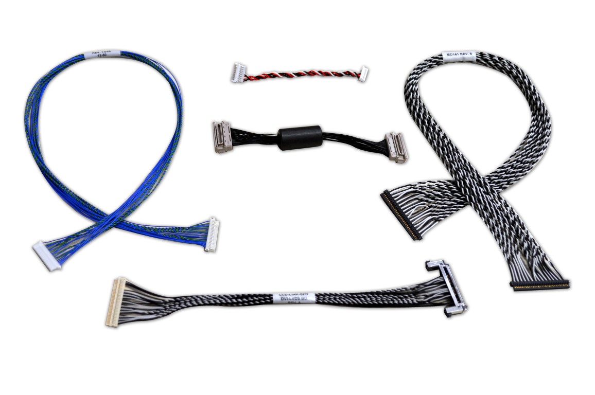
Challenges of High Pin-Count Cable Systems
Modern cable assemblies can contain dozens or even hundreds of conductors. Testing each conductor manually can be extremely time-consuming and prone to human error.
This challenge becomes even greater in industries such as telecommunications, aeroespacial, and data infrastructure where cables often contain complex connector systems.
Automatic Test Equipment (ATE)
To address these challenges, many manufacturers use automatic test equipment (ATE).
ATE systems allow technicians to perform multiple electrical tests simultaneously, incluindo:
- Continuity verification
- Resistance measurement
- Insulation testing
- Pin-out validation
These systems significantly improve testing speed and accuracy while reducing manual labor.
Software-Based Data Monitoring
Automated test systems are often connected to software platforms that record and analyze testing data.
This enables manufacturers to:
- Track quality control results
- Identify recurring defects
- Maintain traceable production records
Such data is extremely valuable for improving product reliability and ensuring compliance with industry standards.
Data Acquisition Systems in Cable Testing
What Is a DAQ System?
UM Data Acquisition System (DAQ) combines hardware sensors and software tools to measure electrical signals and collect performance data.
DAQ systems are commonly used in advanced testing environments where multiple parameters must be monitored simultaneously.
Advantages of DAQ Testing
DAQ systems can monitor a wide range of measurements, incluindo:
- Voltage
- Current
- Temperature
- Pressure
These measurements allow engineers to gain deeper insights into cable performance and detect potential reliability issues.
Long-Term Performance Monitoring
Unlike simple tests performed once during manufacturing, DAQ systems can monitor cable performance over extended periods.
This capability makes them useful for:
- Product development testing
- Reliability validation
- Failure analysis
Long-term testing helps ensure that cable assemblies will perform reliably throughout their operational lifespan.
When Is Continuity Testing Enough?
In many cases, continuity testing is sufficient for verifying basic cable functionality.
It is commonly used for:
- Simple cable assemblies
- Low-voltage wiring systems
- Initial production inspections
- Basic functional verification
No entanto, additional testing becomes necessary when cable assemblies are used in demanding applications such as:
- Automotive electronics
- Aerospace systems
- Medical equipment
- High-speed data transmission
- High-voltage power systems
In these environments, multiple electrical tests are required to ensure safety, reliability, and regulatory compliance.
Conclusão
Continuity testing is one of the most fundamental steps in verifying the electrical integrity of custom cable assemblies. It allows manufacturers to quickly detect open circuits, wiring errors, and incorrect pin-out configurations.
No entanto, continuity testing alone cannot evaluate insulation quality, shielding performance, or long-term reliability. For complex or safety-critical applications, manufacturers often combine continuity testing with additional methods such as Hipot testing, insulation resistance testing, and automated electrical testing systems.
By implementing a comprehensive cable testing strategy, manufacturers can ensure that their custom cable assemblies meet the highest standards of performance, durabilidade, and reliability across a wide range of industries.
Perguntas frequentes
1. What is continuity testing in cable assemblies?
Continuity testing is a basic electrical test used to verify that an uninterrupted electrical path exists within a cable assembly. By sending a small electrical current through the cable, the test confirms whether the circuit is closed and able to conduct electricity from one end to the other.
2. Why is continuity testing important for cable assemblies?
Continuity testing helps manufacturers quickly identify wiring errors, broken conductors, or poor connections. It ensures that electrical signals or power can flow correctly through the cable assembly before the product is installed or used in equipment.
3. Can continuity testing detect all cable assembly problems?
Não, continuity testing cannot detect all issues. While it confirms that a circuit is open or closed, it does not evaluate insulation strength, shielding effectiveness, or high-voltage performance. Additional electrical tests are often required for complete verification.
4. What equipment is commonly used for continuity testing?
Common tools used for continuity testing include digital multimeters, ohmmeters, and specialized cable testing equipment. In manufacturing environments, automated test systems or custom test fixtures are often used for faster and more accurate testing.
5. What is pin-out verification in cable testing?
Pin-out verification ensures that each wire inside a multiconductor cable is connected to the correct pin or terminal in the connector. This prevents crossed wires or incorrect wiring that could damage electronic equipment or cause system failures.
6. What is a Hipot test for cable assemblies?
A Hipot test, also known as a dielectric withstanding voltage test, applies a high voltage across the cable insulation to verify that it can safely withstand electrical stress without leakage or breakdown. This test is commonly used for safety-critical applications.
7. What is insulation resistance testing?
Insulation resistance testing measures the resistance between conductors or between a conductor and the cable shield. High resistance indicates good insulation quality, while low resistance may signal insulation damage or moisture contamination.
8. Why is shielding testing important in cables?
Shielding tests evaluate the electrical integrity of the cable’s shielding or braid layer. Proper shielding helps reduce electromagnetic interference (EMI) and ensures stable signal transmission in environments with electrical noise.
9. What is automated cable testing equipment?
Automated cable testing equipment allows manufacturers to test multiple electrical parameters simultaneously, including continuity, resistência, insulation performance, and pin configuration. These systems improve testing efficiency, accuracy, and production consistency.
10. When is continuity testing sufficient for cable assemblies?
Continuity testing is usually sufficient for simple cable assemblies or basic functional checks. No entanto, for complex systems, high-voltage applications, or critical industries such as automotive, aeroespacial, and medical devices, additional electrical testing is necessary to ensure safety and reliability.
