

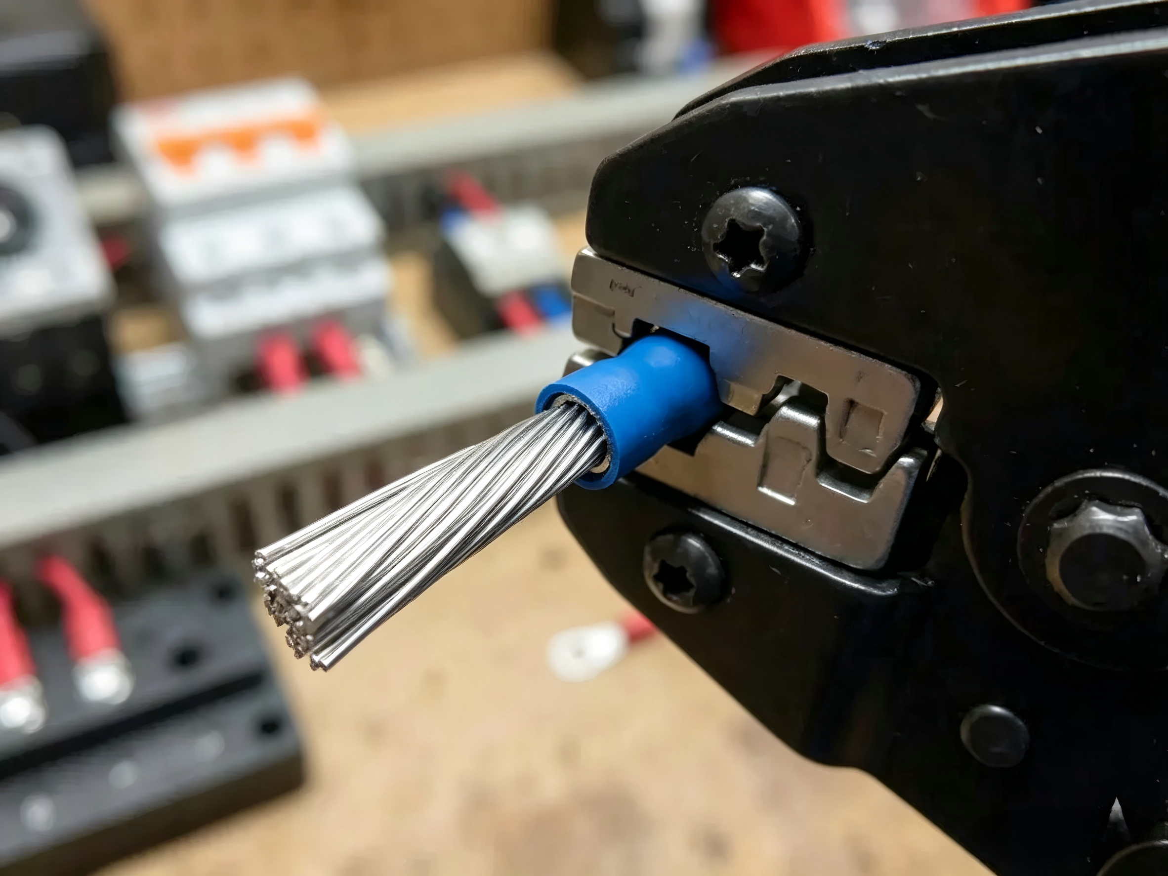
A reliable electrical connection depends not only on the terminal itself, but also on how the terminal is crimped to the wire. In electrical systems, a poor crimp can increase contact resistance, generate heat, reduce mechanical strength, and eventually cause connection failure.
For applications such as automotive wiring, industrial equipment, battery systems, energy storage, EV charging, and power distribution, electrical terminal crimping needs to be controlled carefully. The terminal, wire, crimping tool, and process parameters must work together to create a stable connection.
So, what makes a good crimp terminal connection?
The answer involves more than simply applying pressure to a terminal. Proper terminal design, wire selection, crimp geometry, crimp height, conductor insertion, tooling, and quality inspection all affect the final result.
This guide explains the key considerations in electrical terminal crimping, from terminal design and the crimping process to testing and mass-production quality control.
What Is Electrical Terminal Crimping?
Electrical terminal crimping is a mechanical process used to connect an electrical terminal to a wire or cable. A crimping tool compresses the terminal around the conductor, creating a combination of electrical contact and mechanical retention.
Unlike soldering, a properly designed crimp connection does not rely on solder to hold the conductor in place. The terminal and conductor are mechanically compressed to form a stable connection.
A good crimp should provide two important functions:
- A low and stable electrical resistance
- Sufficient mechanical retention between the terminal and conductor
This makes crimp terminals widely used in wire harnesses, automotive electrical systems, industrial equipment, appliances, battery systems, and other electrical applications.
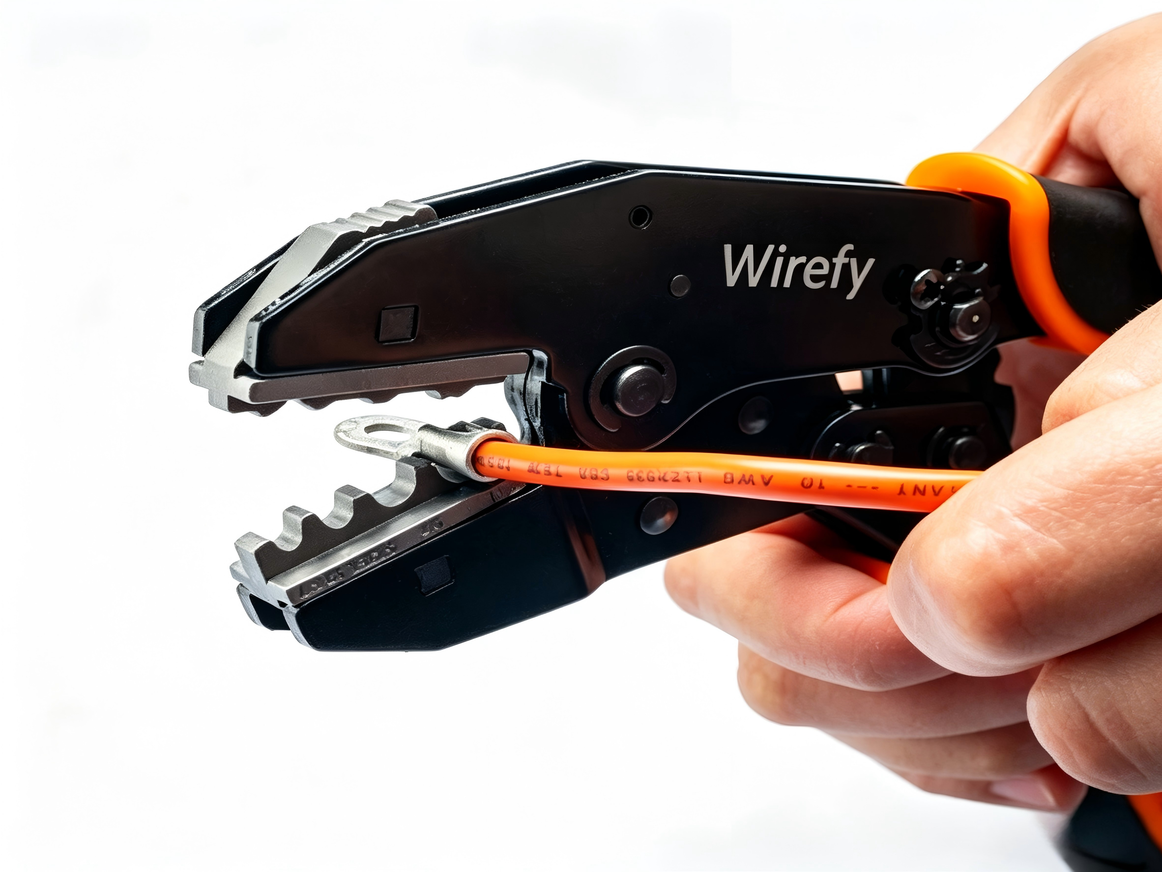
How Does a Crimp Terminal Create an Electrical Connection?
During crimping, the terminal barrel is compressed around the stripped conductor. The deformation creates multiple points of contact between the terminal and the wire strands.
At the same time, the compressed structure prevents the conductor from being easily pulled out.
The final connection depends on several factors, including terminal material, barrel geometry, conductor size, crimp profile, and applied crimp force.
Why Is Crimp Quality Important?
A visually acceptable crimp is not necessarily an electrically reliable crimp.
Poor crimping can result in:
- Increased contact resistance
- Excessive temperature rise
- Voltage drop
- Weak pull-out strength
- Broken conductor strands
- Intermittent electrical connections
- Terminal deformation
- Premature product failure
For this reason, crimp quality should be controlled through both visual inspection and measurable electrical and mechanical tests.
1. Terminal Design Considerations Before Crimping
Good crimping starts with good terminal design. If the terminal barrel is not properly matched to the conductor and tooling, even a well-operated crimping machine may not produce a reliable connection.
Terminal Material
Common materials for electrical terminals include copper, brass, and phosphor bronze.
Copper provides excellent electrical conductivity and is widely used where efficient current transmission is important.
Brass provides a balance of electrical conductivity, mechanical strength, corrosion resistance, and manufacturability. It is commonly used for various stamped electrical terminals.
Phosphor bronze offers good mechanical strength, spring properties, and fatigue resistance. It can be useful for contact components where stable contact force is important.
Material selection should be based on the electrical, mechanical, environmental, and manufacturing requirements of the application.
Terminal Barrel Design
The terminal barrel is the section that receives and holds the conductor. Its dimensions and geometry have a direct effect on crimp performance.
Important design parameters include:
- Barrel diameter
- Barrel length
- Wall thickness
- Crimp area
- Material hardness
- Terminal geometry
A barrel that is too large may not provide sufficient compression, while a barrel that is too small may excessively deform the conductor.
Match Terminal Design to Wire Size
Terminal selection should always correspond to the conductor cross-section and construction.
For example, a terminal designed for a specific wire range may not perform correctly when used with a conductor outside that range.
The terminal barrel, conductor size, insulation diameter, and crimp tooling should therefore be evaluated as one system.
2. Choosing the Right Wire and Terminal Combination
Before beginning the crimping process, the wire and terminal need to be compatible.
Wire Cross-Section
The conductor cross-section is one of the most important selection factors.
Using a terminal designed for a smaller conductor can cause excessive compression or conductor damage. Using a terminal that is too large can result in insufficient compression and increased electrical resistance.
The correct terminal should therefore be selected according to the actual conductor size and customer or application requirements.
Stranded vs. Solid Wire
Many electrical terminal applications use stranded wire because of its flexibility and resistance to mechanical fatigue.
Stranded conductors require careful stripping and crimping because damaged or missing strands can reduce the effective conductor area.
The crimping process should compress the strands consistently without cutting or excessively deforming them.
Terminal and Wire Compatibility
A complete compatibility check may include:
- Conductor cross-section
- Number and size of strands
- Insulation diameter
- Terminal barrel dimensions
- Crimp profile
- Required mechanical retention
- Electrical requirements
Choosing the terminal and wire together helps establish a stable crimping process before mass production.
3. Electrical Terminal Crimping Process
A controlled crimping process typically consists of several steps.
Step 1 – Wire Preparation
The wire is first cut to the required length and stripped to expose the conductor.
The stripping process needs to remove the insulation without damaging conductor strands.
Important controls include:
- Strip length
- Cut length
- Conductor condition
- Insulation condition
Damaged strands can reduce both electrical and mechanical performance.
Step 2 – Terminal Positioning
The stripped conductor is inserted into the terminal barrel.
The conductor needs to reach the correct insertion position before crimping.
Incorrect positioning can lead to:
- Incomplete conductor compression
- Poor electrical contact
- Reduced pull-out force
- Incorrect insulation support
For automated production, terminal positioning and wire insertion can be controlled using dedicated applicators and production equipment.
Step 3 – Crimping
The terminal is then compressed using the appropriate crimping tool and die.
The tooling profile must match the terminal design and conductor requirements.
During production, important parameters can include:
- Crimp height
- Crimp width
- Crimp force
- Tooling position
- Terminal positioning
Step 4 – Insulation Crimp
Some terminal designs include an additional insulation crimp.
The insulation crimp provides strain relief and helps reduce movement between the wire and terminal.
It should support the wire without excessively damaging or cutting the insulation.
Step 5 – Visual and Dimensional Inspection
After crimping, the connection should be inspected for:
- Correct crimp shape
- Proper wire insertion
- Conductor visibility where required
- Terminal deformation
- Insulation position
- Crimp height and width
Visual inspection is an important first step, but it should be combined with other quality tests for critical applications.
4. Key Crimping Parameters to Control
Consistent crimp dimensions are essential for repeatable electrical terminal performance.
Crimp Height
Crimp height is the measured height of the compressed terminal barrel after crimping.
It is an important process-control parameter because it provides an indication of how much the terminal has been compressed.
If the crimp is too loose, the conductor may not be adequately secured.
If the crimp is excessively tight, conductor strands may be damaged and the terminal may be over-deformed.
The correct crimp height should be established according to the terminal design, conductor, tooling, and applicable requirements.
Crimp Width
Crimp width is another important dimensional parameter.
The correct width depends on the terminal geometry and tooling design. Consistent crimp width helps maintain a repeatable connection between the terminal and conductor.
Conductor Insertion
The conductor must be inserted into the correct location before crimping.
Incomplete insertion can reduce both electrical contact and mechanical retention.
During production, operators or automated equipment should verify that the conductor reaches the specified position.
Crimp Force
Crimp force can be monitored in automated or controlled production processes.
Unexpected changes in crimp force may indicate:
- Tool wear
- Incorrect terminal positioning
- Material variation
- Conductor problems
- Machine issues
Monitoring crimp force can therefore help identify process abnormalities before large quantities of terminals are produced.
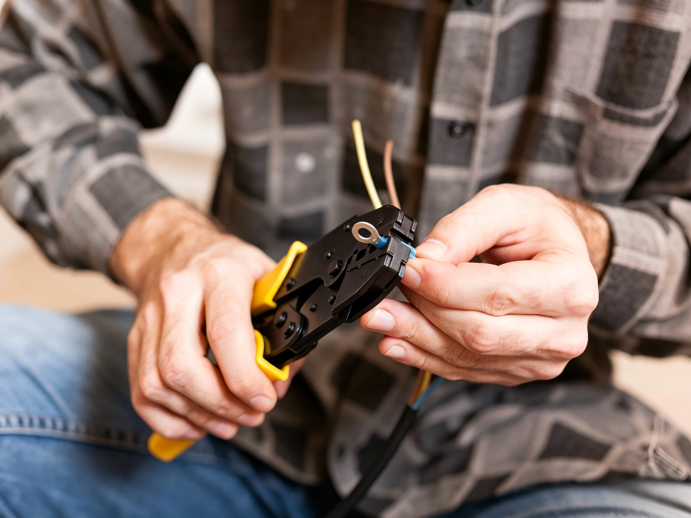
5. Common Electrical Terminal Crimping Defects
Crimping defects can result from incorrect terminal selection, improper tooling, material variation, or inconsistent process control.
| Crimping Defect | Possible Cause | Potential Result |
|---|---|---|
| Under-crimping | Insufficient compression | High resistance or weak retention |
| Over-crimping | Excessive compression | Damaged conductor or terminal |
| Incomplete wire insertion | Incorrect positioning | Poor electrical and mechanical connection |
| Broken wire strands | Improper stripping or crimping | Reduced conductor performance |
| Terminal deformation | Incorrect tooling | Poor mating or assembly |
| Inconsistent crimp | Tool wear or process variation | Unstable product quality |
How to Prevent Crimping Defects
Manufacturers can reduce crimping defects through:
- Correct terminal and wire selection
- Proper tooling design
- Controlled crimp parameters
- First-piece inspection
- Regular tooling maintenance
- Operator training
- In-process inspection
- Electrical and mechanical testing
Tool condition is particularly important in high-volume stamping and crimping operations because gradual die wear can change the final crimp geometry.
6. Electrical Terminal Crimping Quality Requirements
A good crimp needs to satisfy mechanical, electrical, and dimensional requirements.
Mechanical Requirements
Mechanical testing can include pull-out or tensile testing.
The purpose is to determine whether the conductor remains securely attached to the terminal under the required mechanical load.
The required pull-out force depends on the terminal design, conductor size, application, and applicable specifications.
Electrical Requirements
Electrical performance can be evaluated through:
- Contact resistance
- Voltage drop
- Current-carrying capability
- Temperature rise
A low-resistance connection is particularly important for high-current applications because resistance contributes directly to heat generation.
The relationship can be expressed as:
P = I²R
where P represents heat generated by resistance, I is current, and R is resistance.
Even a relatively small increase in resistance can become significant when current is high.
Dimensional Requirements
Dimensional inspection may include:
- Crimp height
- Crimp width
- Terminal dimensions
- Wire position
- Overall terminal geometry
Maintaining dimensional consistency helps ensure stable performance across mass-produced parts.
7. How Are Crimp Terminals Tested?
Testing requirements depend on the terminal design and application.
Crimp Pull Force Test
A pull-force test evaluates the mechanical connection between the conductor and terminal.
It can help identify under-crimping, incorrect terminal selection, or other process problems.
Contact Resistance Test
Contact resistance testing evaluates the electrical quality of the connection.
A stable, low-resistance connection is important for reducing voltage drop and heat generation.
Cross-Section Analysis
Cross-section analysis is a useful method for examining the internal quality of a crimp.
The crimped section can be cut and inspected to evaluate:
- Conductor compression
- Strand distribution
- Terminal deformation
- Crimp symmetry
- Internal gaps or abnormalities
Unlike visual inspection of the outside of the terminal, cross-section analysis provides information about the internal crimp structure.
Temperature-Rise Testing
Temperature-rise testing is particularly relevant to high-current terminals.
A terminal can be tested under representative electrical loads while temperature is monitored at critical locations.
This helps determine whether the terminal and crimp connection can carry the required current without excessive temperature rise.
8. Crimping Quality Control in Mass Production
Consistent quality requires more than checking finished terminals.
Incoming Material Inspection
Manufacturers should control incoming materials such as:
- Copper
- Brass
- Phosphor bronze
- Plating materials
Material thickness, surface condition, and other specified characteristics should be verified according to the production requirements.
Tooling and Die Control
Tooling has a direct influence on terminal dimensions and crimp quality.
Regular maintenance can help prevent problems caused by:
- Die wear
- Dimensional changes
- Misalignment
- Excessive machine variation
In-Process Inspection
Production inspection can include:
- Crimp height
- Crimp width
- Visual appearance
- Wire position
- Pull-force checks
- Electrical resistance checks
The inspection frequency should be established according to the product and production requirements.
Final Inspection
Final inspection can verify:
- Product dimensions
- Electrical performance
- Mechanical performance
- Plating condition
- Packaging
- Traceability
A controlled inspection system helps ensure that the quality established during development is maintained during mass production.
9. How Terminal Design Affects Crimping Performance
Crimping problems are not always caused by the crimping machine or operator.
Terminal design itself has a significant influence on the final connection.
Factors such as:
- Terminal thickness
- Barrel geometry
- Material hardness
- Crimp area
- Contact structure
- Tooling design
can affect crimp performance.
This is why terminal design and tooling development should be considered together.
For OEM projects, manufacturers can evaluate the terminal design, wire specification, and crimping requirements before developing production tooling.
Good crimping starts with a terminal design that is suitable for the intended conductor and application.
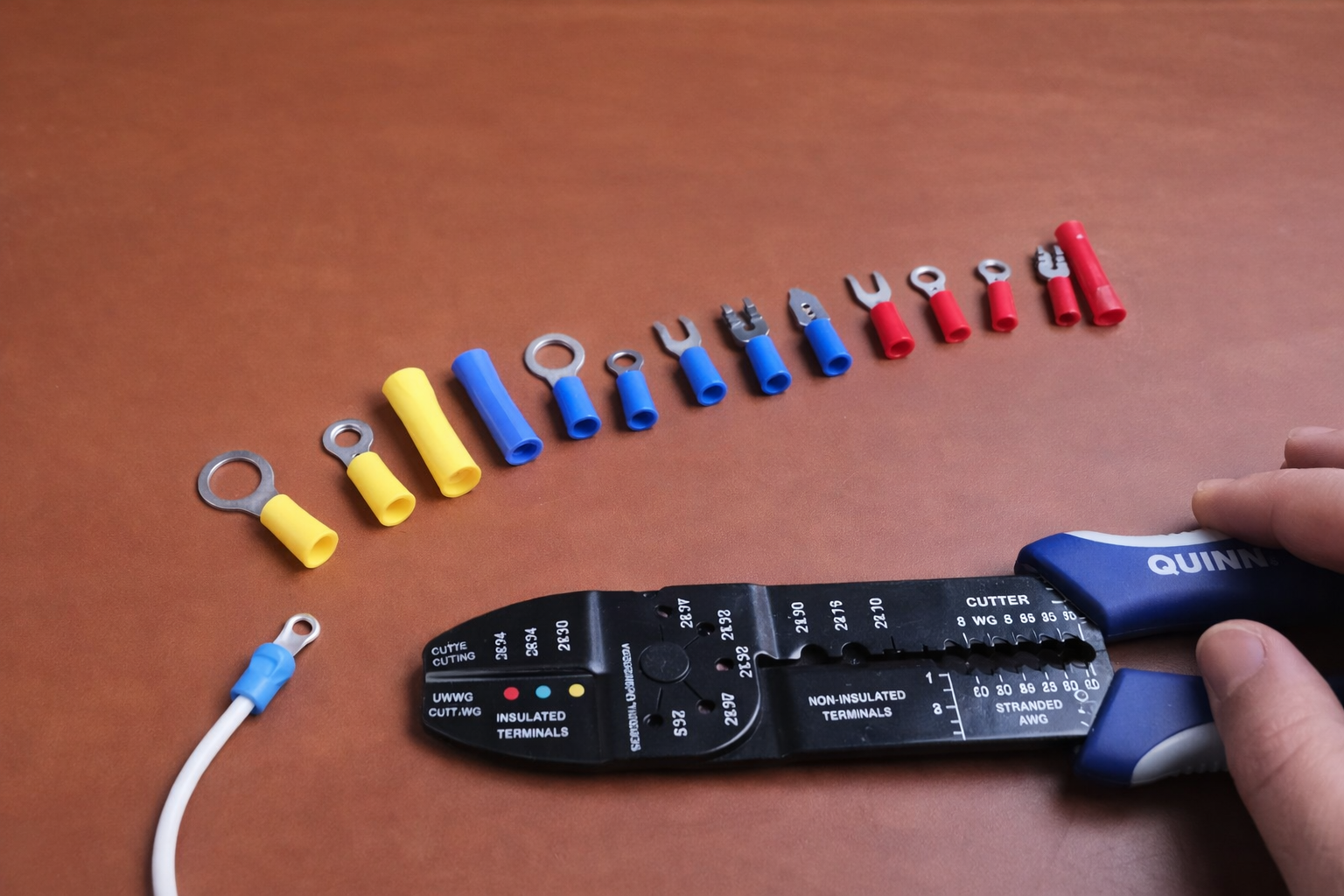
10. When Do You Need a Custom Crimp Terminal?
Standard terminals can be suitable when the wire size, current requirement, mounting method, and installation conditions match an existing design.
However, a custom crimp terminal may be required when standard products cannot meet the application requirements.
Customization may be appropriate when you need:
- A non-standard wire size
- Special terminal dimensions
- Limited installation space
- Specific crimp dimensions
- High-current capability
- Special mounting holes
- Customized material
- Specific plating
- Special contact geometry
- High-volume production tooling
What Can a Custom Terminal Manufacturer Provide?
An experienced electrical terminal manufacturer can support the project from initial design through mass production.
The process may include:
Terminal Design → Tooling → Precision Stamping → Plating → Inspection → Mass Production
For custom crimp terminals, early cooperation between the customer and manufacturer can help optimize terminal geometry, material selection, crimp dimensions, and tooling before production begins.
This can be particularly valuable for OEM and wire harness projects with specific electrical, mechanical, or dimensional requirements.
Electrical Terminal Crimping Quality Checklist
Before approving a crimp terminal for production, engineers and purchasing teams can review the following points:
- Correct terminal selected
- Correct wire size
- Correct stripping length
- No damaged conductor strands
- Full conductor insertion
- Correct crimp height
- Correct crimp width
- Proper insulation support
- Required pull-out force achieved
- Contact resistance within specification
- Acceptable crimp cross-section
- Terminal dimensions within tolerance
- Tooling condition verified
- Required electrical testing completed
This checklist can help identify potential problems before they affect mass production.
Choose an Experienced Electrical Terminal Manufacturer
Reliable electrical terminal crimping requires more than a suitable crimping machine. The terminal design, material, wire, tooling, process parameters, and inspection methods all contribute to the final connection.
For OEM and wire harness applications, working with an experienced terminal manufacturer from the design stage can help ensure that the terminal and crimping process are developed together.
Qianwei Precision provides custom electrical terminal manufacturing services covering:
Terminal Design → Tooling → Precision Stamping → Plating → Inspection → Mass Production
For a custom crimp terminal project, customers can provide information such as:
- Wire size
- Terminal drawing or sample
- Required current
- Material requirements
- Plating requirements
- Crimp specifications
- Application environment
- Estimated production volume
With these details, the manufacturer can evaluate the terminal design and production requirements more efficiently.
Need a custom crimp terminal for your electrical or wire harness application? Contact Qianwei Precision to discuss your terminal design and production requirements.
FAQs
What is electrical terminal crimping?
Electrical terminal crimping is a mechanical process that joins an electrical terminal to a wire by compressing the terminal around the conductor. A properly designed crimp provides both electrical conductivity and mechanical retention.
Why is crimping important for electrical terminals?
Crimping quality directly affects contact resistance, mechanical strength, temperature rise, and long-term connection reliability. Poor crimping can lead to increased resistance, overheating, or wire pull-out.
What is crimp height?
Crimp height is the measured height of the terminal barrel after it has been compressed around the conductor. It is an important dimensional parameter for controlling crimp consistency.
How do you test a crimp terminal?
Common tests include crimp pull-force testing, contact resistance testing, dimensional inspection, visual inspection, cross-section analysis, and temperature-rise testing where applicable.
What causes a crimp terminal to overheat?
Excessive heat can result from high contact resistance, under-crimping, poor conductor insertion, damaged wire strands, loose connections, inadequate contact area, or excessive electrical load.
What causes a weak crimp?
A weak crimp can be caused by incorrect terminal selection, insufficient compression, improper wire insertion, incorrect crimp tooling, damaged conductor strands, or process variation.
How do you choose the right crimp terminal?
Start with the conductor size and construction, then consider the required current, terminal material, barrel dimensions, crimping method, mechanical requirements, operating environment, and applicable specifications.
Can electrical terminals be customized?
Yes. Custom electrical terminals can be developed with specific materials, dimensions, barrel designs, crimp structures, mounting configurations, plating, and tooling according to the application requirements.

