


Flexible copper busbars are widely used in battery systems, energy storage equipment, electric vehicles, power distribution units, and industrial electrical assemblies. They provide a reliable way to connect electrical components while accommodating limited installation space, vibration, and certain types of mechanical movement.
However, manufacturing a reliable flexible copper busbar involves more than selecting conductive copper and forming it into the required shape. Material properties, layer configuration, connection-end design, surface treatment, and inspection procedures all influence the final product’s electrical and mechanical performance.
For OEM manufacturers and electrical engineers, understanding these manufacturing factors helps reduce design risks, improve assembly compatibility, and select the right supplier for custom applications.
This guide explains the key stages of flexible copper busbar manufacturing, from material selection and bending to plating, quality control, and supplier evaluation.
1. What Is a Flexible Copper Busbar?
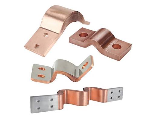
A flexible copper busbar is an electrical conductor designed to carry current while accommodating movement, vibration, or installation constraints. Unlike a conventional rigid copper busbar, which is typically made from a solid copper bar or plate, a flexible design can use multiple thin copper foils or other flexible conductive structures.
Depending on the application, the flexible section may be combined with rigid connection ends, drilled mounting holes, or specially formed terminals.

Structure and Working Principle
One common construction consists of multiple thin copper foils joined at their connection ends. The individual foils can move relative to one another along the flexible section, allowing the busbar to bend more easily than a solid copper bar of comparable cross-sectional area.
Other designs may use braided copper conductors or alternative flexible structures. The appropriate construction depends on current requirements, available space, mechanical movement, and the connection method.
The flexible section accommodates movement, while the connection ends provide the interfaces needed to connect batteries, busbars, electrical terminals, or other conductive components.
Flexible Copper Busbars vs. Rigid Copper Busbars
Rigid copper busbars are suitable for fixed connections where the installation geometry remains relatively stable. They are commonly used in switchgear, distribution panels, and electrical cabinets.
Flexible copper busbars are useful when a connection must accommodate vibration, thermal expansion, assembly tolerances, or limited installation space.
The choice depends on the application rather than on flexibility alone. Engineers should consider current capacity, voltage requirements, temperature rise, available space, mechanical loads, and connection resistance before selecting either design.
Common Applications
Flexible copper busbars are commonly considered for:
- Battery systems: Connecting battery modules, terminals, and power distribution components.
- Battery energy storage systems (BESS): Providing electrical connections within battery racks and power conversion equipment.
- Electric vehicles: Connecting battery packs and selected high-current electrical assemblies.
- Industrial power equipment: Accommodating connections where vibration or installation tolerances are relevant.
- Power distribution systems: Connecting components in compact electrical enclosures and equipment assemblies.
The exact construction and specifications should be matched to the electrical and mechanical requirements of each application.
2. Material Selection for Flexible Copper Busbar Manufacturing
Material selection is one of the first decisions in flexible copper busbar manufacturing. Copper offers high electrical conductivity and good formability, but different copper grades and product configurations can have different mechanical and electrical characteristics.
Copper Grades and Electrical Conductivity
Copper is widely used for busbars because of its ability to conduct electricity efficiently. Common options include high-conductivity copper grades such as C11000 and other grades selected according to regional standards, manufacturing requirements, and customer specifications.
When comparing materials, manufacturers and engineers should evaluate:
- Electrical conductivity and resistivity
- Mechanical strength and ductility
- Formability and suitability for joining
- Material thickness and dimensional tolerances
- Compatibility with the selected surface treatment
A material with excellent conductivity is not automatically the best choice for every design. The material must also be suitable for the required forming process and operating environment.
Copper Foil Thickness and Layer Configuration
For laminated flexible copper busbars, the thickness and number of copper foil layers affect the overall structure.
Thinner foils can improve flexibility, while the combined copper cross-sectional area contributes to the conductor’s electrical performance. However, flexibility and current capacity cannot be determined from layer count alone.
Engineers should consider the total conductive cross-section, operating current, allowable temperature rise, cooling conditions, ambient temperature, and installation method.
For example, a compact battery connection may require a different combination of foil thickness, width, and layer count from a flexible connection used in industrial power distribution equipment.
The final configuration should be established through electrical and mechanical design rather than selecting dimensions solely by appearance.
How Material Selection Affects Performance
Material properties influence several aspects of the finished busbar.
Electrical conductivity affects resistance and heat generation. Ductility influences how the copper behaves during forming. Thickness and layer arrangement affect flexibility, while the quality of the connection ends influences contact performance.
Material selection should therefore be considered together with the intended bending geometry, joining method, surface treatment, and operating conditions.
Selecting Materials for Different Environments
Battery systems, industrial electrical equipment, and outdoor installations may face different temperature, humidity, vibration, and corrosion conditions.
In addition to selecting the copper grade, engineers should determine whether the connection requires tin plating, silver plating, another surface treatment, or no additional coating.
The decision should follow the electrical interface requirements, environmental exposure, and applicable customer specifications.
3. The Flexible Copper Busbar Manufacturing Process
The manufacturing process varies according to the busbar’s structure, dimensions, connection method, and application. A typical production workflow may include design review, copper preparation, layer assembly, connection-end processing, finishing, and inspection.
Step 1: Design Review and Technical Specification
Before production begins, the manufacturer reviews the customer’s drawing or technical specification.
Important details include:
- Overall length, width, and thickness
- Copper grade and required cross-sectional area
- Number and thickness of copper foil layers
- Connection-end dimensions and hole positions
- Required bending shape and installation clearances
- Surface treatment and plating requirements
- Electrical, mechanical, and environmental specifications
A clear design review helps identify potential manufacturing problems before tooling or production starts.
For OEM projects, it is also useful to confirm the expected annual volume, prototype requirements, packaging method, and inspection criteria.
Step 2: Copper Foil Cutting and Preparation
Copper foil is prepared to the dimensions specified in the design. Cutting accuracy is important because incorrect dimensions can affect layer alignment, final thickness, and connection-end geometry.
The prepared material should also be checked for visible damage, contamination, burrs, or other conditions that could affect subsequent processing.
Depending on the manufacturing method, additional preparation may be required to ensure suitable surface conditions for joining.
Step 3: Layer Stacking and Bonding
For laminated flexible copper busbars, multiple copper foils are arranged into the required stack.
The connection ends may then be joined using a suitable process, such as pressure welding or another qualified joining method, depending on the product design.
The joining process must produce an electrically conductive and mechanically reliable connection without compromising the required flexibility of the free section.
Not every flexible copper busbar uses the same bonding process. Some designs use braided conductors or alternative constructions, so the manufacturing route should be selected according to the actual product structure.
Step 4: Terminal Forming and Connection-End Processing
The connection ends must fit the equipment to which the busbar will be attached. Depending on the design, processing may include forming, hole punching or drilling, trimming, and other dimensional operations.
Hole positions, mounting surfaces, contact areas, and overall geometry should be controlled carefully. Small deviations can make assembly difficult or affect the quality of the electrical connection.
For custom projects, confirming the connection interface during the design stage helps reduce rework and assembly problems.
Step 5: Dimensional Finishing and Surface Preparation
After the main forming and joining operations, the busbar may undergo trimming, deburring, cleaning, or other finishing processes.
The goal is to achieve the required dimensions and surface condition while avoiding damage to the copper layers or connection areas.
Before plating or final inspection, the manufacturer should verify that the relevant surfaces are suitable for the next process.
4. Bending and Forming: Achieving the Required Shape
Bending is an important consideration when designing a flexible copper busbar for compact electrical equipment. The purpose is not simply to produce a particular shape, but to ensure that the finished part fits the installation space without damaging its conductive structure.
Common Bending and Forming Methods
Depending on the construction, manufacturing may involve controlled bending of the flexible section, forming of rigid connection ends, or shaping of the copper conductor to match the required installation geometry.
Laminated copper foil busbars behave differently from solid copper bars. Their flexibility depends on foil thickness, layer arrangement, joining configuration, and the direction and extent of bending.
For this reason, the forming process should be developed around the actual product rather than applying a single bending rule to every design.
Bend Radius and Installation Space
The required bend radius depends on the busbar structure and the manufacturer’s design limits. Excessive bending or repeated movement beyond the intended range may damage the copper foil, affect the connection area, or shorten service life.
Engineers should consider:
- Available installation space
- Required bend direction and angle
- Distance between connection points
- Clearance from nearby components
- Expected vibration or relative movement
- Accessibility during assembly and maintenance
Where the busbar will be installed in a battery pack or compact power assembly, confirming the actual mounting geometry is particularly important.
Preventing Cracks, Deformation, and Layer Damage
Potential forming defects include local deformation, damaged foil edges, misaligned layers, and damage near the joined ends.
Prevention begins with a suitable design and continues through controlled processing and dimensional inspection.
A prototype can help verify the intended geometry before mass production. For more demanding applications, the assembly should also be evaluated under the relevant mechanical and environmental conditions.
Custom Shapes for Compact Assemblies
Custom flexible copper busbars can be designed around the available mounting space and connection interfaces. Depending on the application, a design may include different overall lengths, connection-end dimensions, mounting holes, or specific bend configurations.
Providing an accurate drawing or sample allows the manufacturer to assess feasibility and identify potential conflicts before production.
5. Surface Plating and Corrosion Protection
Surface treatment can affect the contact performance, oxidation resistance, and environmental suitability of a flexible copper busbar. The appropriate finish depends on where and how the busbar will be used.
Why Do Flexible Copper Busbars Need Surface Treatment?
Copper can form surface oxides when exposed to the environment. Depending on the contact design and operating conditions, surface oxidation or contamination may influence electrical contact performance over time.
A suitable plating or protective treatment can help address these concerns. However, the effectiveness of a finish depends on the plating process, coating thickness, surface preparation, and service environment.
Not every busbar requires the same treatment. The requirements should be defined according to the connection interface and the applicable specification.
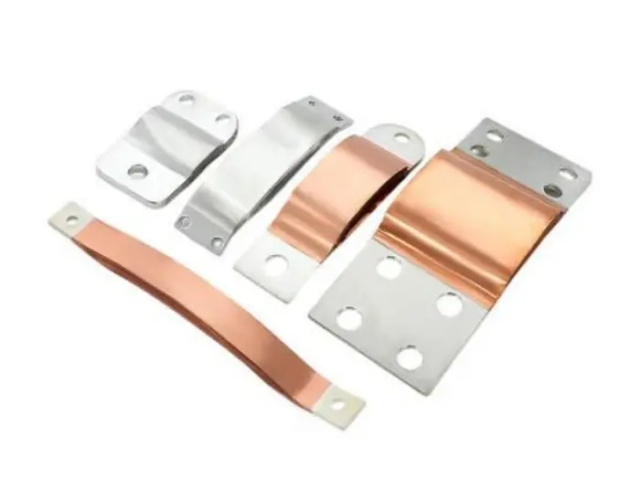
Tin Plating, Silver Plating, and Other Options
Tin plating is used in many electrical connection applications because it can provide a practical contact finish and help protect the underlying copper from direct environmental exposure.
Silver plating offers high electrical conductivity and may be selected for specific contact applications where the design and operating conditions justify it.
Other surface treatments may be appropriate for specialized requirements. The final choice should consider contact resistance, operating temperature, environmental exposure, mating materials, cost, and applicable specifications.
No single finish is ideal for every application. For example, a connection operating at elevated temperatures or in a demanding environment may require additional evaluation of coating stability and contact behavior.
Plating Thickness and Coverage
Plating requirements should specify the applicable coating, thickness, and areas to be treated. Connection surfaces may have different requirements from other parts of the busbar.
Depending on the design, inspection may include coating-thickness measurement, visual examination, and verification of the specified plating coverage.
For laminated structures, the plating process must also be compatible with the product geometry and intended contact surfaces.
Choosing a Suitable Plating Process
Before confirming the surface treatment, OEM buyers should provide the operating environment, contact requirements, mating material, and any relevant technical standards.
These details help the manufacturer recommend an appropriate finish and establish suitable acceptance criteria.
6. Quality Control in Flexible Copper Busbar Manufacturing
Quality control should cover the manufacturing process and the finished product. A busbar may have the correct external dimensions but still fail to meet requirements for electrical resistance, connection integrity, or plating quality.
A practical inspection plan should therefore be based on the product drawing, customer specifications, and the risks associated with its intended application.
Dimensional and Visual Inspection
Dimensional inspection verifies that the busbar matches the approved drawing. Typical checkpoints include overall length, width, thickness, mounting-hole positions, and connection-end dimensions.
Visual inspection can identify burrs, cracks, scratches, surface contamination, deformation, and other visible defects.
The inspection method and acceptance limits should be defined before production to ensure consistent evaluation.
Electrical Resistance and Conductivity Testing
Electrical performance is a key consideration for high-current connections.
The resistance of the finished busbar depends on the copper material, conductive cross-section, current path, connection design, and quality of the joined areas. Excessive resistance can contribute to heat generation under load.
Where required, manufacturers may perform resistance measurements or other specified electrical tests. Results should be evaluated against the applicable design limits and test conditions.
For high-current applications, temperature-rise testing under defined operating conditions may also be necessary. Such testing should use an appropriate test setup and acceptance criteria rather than relying on an assumed current rating.
Bonding Integrity and Mechanical Inspection
For laminated busbars, the joined connection ends must provide the required electrical and mechanical integrity.
Inspection may include visual checks, dimensional verification, and suitable mechanical or destructive tests where specified. The choice depends on the joining method, product structure, and customer requirements.
A reliable inspection plan should identify the characteristics that are critical to performance and verify them using appropriate methods.
Plating Thickness and Surface Quality
Where plating is required, inspection may cover coating thickness, appearance, coverage, and other specified properties.
The inspection method should be appropriate for the coating and substrate. For example, thickness measurement methods must be suitable for the materials and geometry being evaluated.
Acceptance limits should follow the drawing or agreed technical specification.
Traceability and Batch Consistency
For OEM production, quality management extends beyond the inspection of individual parts.
Material identification, production records, inspection results, and batch traceability can help manufacturers investigate quality issues and maintain consistency between production runs.
Customers may also require first-article inspection, sample approval, or additional documentation before mass production.
A clear agreement on inspection requirements at the beginning of a project helps avoid misunderstandings during delivery and acceptance.
7. Common Manufacturing Defects and How to Prevent Them
Understanding common defects helps OEM buyers assess manufacturing risks and communicate technical requirements more effectively.
| Potential defect | Possible causes | Preventive measures |
|---|---|---|
| Incorrect dimensions | Cutting, forming, or setup variation | Confirm drawings, process settings, and dimensional inspection |
| Damaged copper foil | Improper handling or excessive deformation | Control handling and forming; inspect critical areas |
| Poor connection-end bonding | Unsuitable joining parameters or surface preparation | Qualify the joining process and verify connection integrity |
| Uneven plating | Inadequate surface preparation or process variation | Control plating conditions and inspect coating thickness where required |
| High electrical resistance | Insufficient conductive area, poor contact, or defective joining | Review the design and perform specified electrical tests |
| Assembly misalignment | Incorrect hole positions or connection-end geometry | Verify mounting interfaces and approve prototypes before mass production |
These defects do not always have a single cause. For example, high resistance may result from the conductor design, connection interface, or manufacturing process. Corrective action should therefore be based on inspection results and technical analysis.
For custom flexible copper busbars, reviewing the design before production and validating the prototype can help identify issues early, when they are generally easier to correct.
8. How to Choose a Custom Flexible Copper Busbar Manufacturer
Selecting a supplier involves more than comparing unit prices. OEM buyers should evaluate whether the manufacturer can understand the design, meet the required specifications, and maintain quality throughout production.
Material and Manufacturing Capabilities
Confirm that the supplier can source the specified copper material and manufacture the required structure. Ask about the processes relevant to the actual design, including cutting, joining, forming, surface treatment, and finishing.
Not every supplier offers every process in-house. Where operations are outsourced, buyers should understand how process control and quality verification are managed.
Custom Dimensions and Connection Design
The supplier should be able to review drawings and confirm whether the proposed dimensions, mounting interfaces, and forming requirements are manufacturable.
For new projects, technical communication during design review can help reduce unnecessary revisions and assembly problems.
Quality Assurance and Inspection Records
Ask which characteristics are inspected, how acceptance criteria are established, and what documentation is available.
Depending on the application, requirements may include dimensional reports, electrical test results, coating inspection records, material documentation, or batch traceability.
The supplier’s actual capabilities should be verified against the needs of the project.
Prototype Development and Mass Production
Prototype validation allows the buyer to check fit, dimensions, connection interfaces, and other relevant performance characteristics before committing to full-scale production.
Once the sample is approved, production controls should help maintain consistency with the approved design.
Buyers should also confirm production capacity, lead time, packaging, and any special handling requirements.
Technical Communication
A capable manufacturing partner should be able to clarify incomplete specifications, identify potential manufacturing risks, and communicate realistic production requirements.
This is particularly important for custom electrical components, where a small difference in connection geometry or installation conditions can affect the suitability of the final product.
9. FAQs
What materials are used to manufacture flexible copper busbars?
Flexible copper busbars commonly use high-conductivity copper in the form of thin foils, laminated layers, or other suitable conductor structures. The material grade and dimensions depend on the required electrical performance, mechanical flexibility, manufacturing process, and operating environment.
How are flexible copper busbars formed and bent?
The forming process depends on the busbar’s construction. Laminated copper foil designs may use controlled shaping of the flexible section and separate processing of the connection ends. The allowable bend geometry should be determined according to the structure and design requirements.
Which plating is suitable for flexible copper busbars?
Tin plating and silver plating are common options for electrical applications. The choice depends on contact requirements, operating temperature, environmental exposure, mating materials, and cost. The required coating thickness and coverage should be specified for the intended application.
How is the quality of a flexible copper busbar tested?
Inspection may include dimensional and visual checks, electrical resistance measurements, connection-integrity tests, and plating-thickness verification. Temperature-rise or other performance tests may also be required for particular applications. The final inspection plan should follow the approved drawing and customer specifications.
Can flexible copper busbars be customized for specific applications?
Yes. Depending on the manufacturer’s capabilities, flexible copper busbars can be customized in terms of dimensions, copper layer configuration, connection-end geometry, mounting holes, bending shape, and surface finish. Technical drawings or samples help the manufacturer assess feasibility.
What information is needed to request a quote for a custom flexible copper busbar?
Useful information includes the product drawing or sample, copper material requirements, dimensions, expected current, operating environment, connection details, surface treatment, order quantity, and target delivery schedule. If some specifications are not yet finalized, the buyer can provide the available design information for an initial feasibility review.
10. Conclusion: Reliable Manufacturing Starts with the Right Process
Flexible copper busbar manufacturing requires careful coordination between material selection, conductor configuration, forming, surface treatment, and quality control.
The right copper grade and layer arrangement help establish the required electrical and mechanical characteristics. Controlled bending and connection-end processing support installation accuracy, while suitable plating and inspection procedures help verify the finished product against its specifications.
For OEM buyers, working with a manufacturer that understands technical drawings, custom requirements, and production quality can help reduce design risks and improve consistency.
Looking for a custom flexible copper busbar for your electrical application?
Contact Qianwei Precision to discuss your electrical component requirements. Share your drawings, dimensions, connection details, operating conditions, and expected order quantity to begin a technical review and explore a suitable manufacturing solution.

