

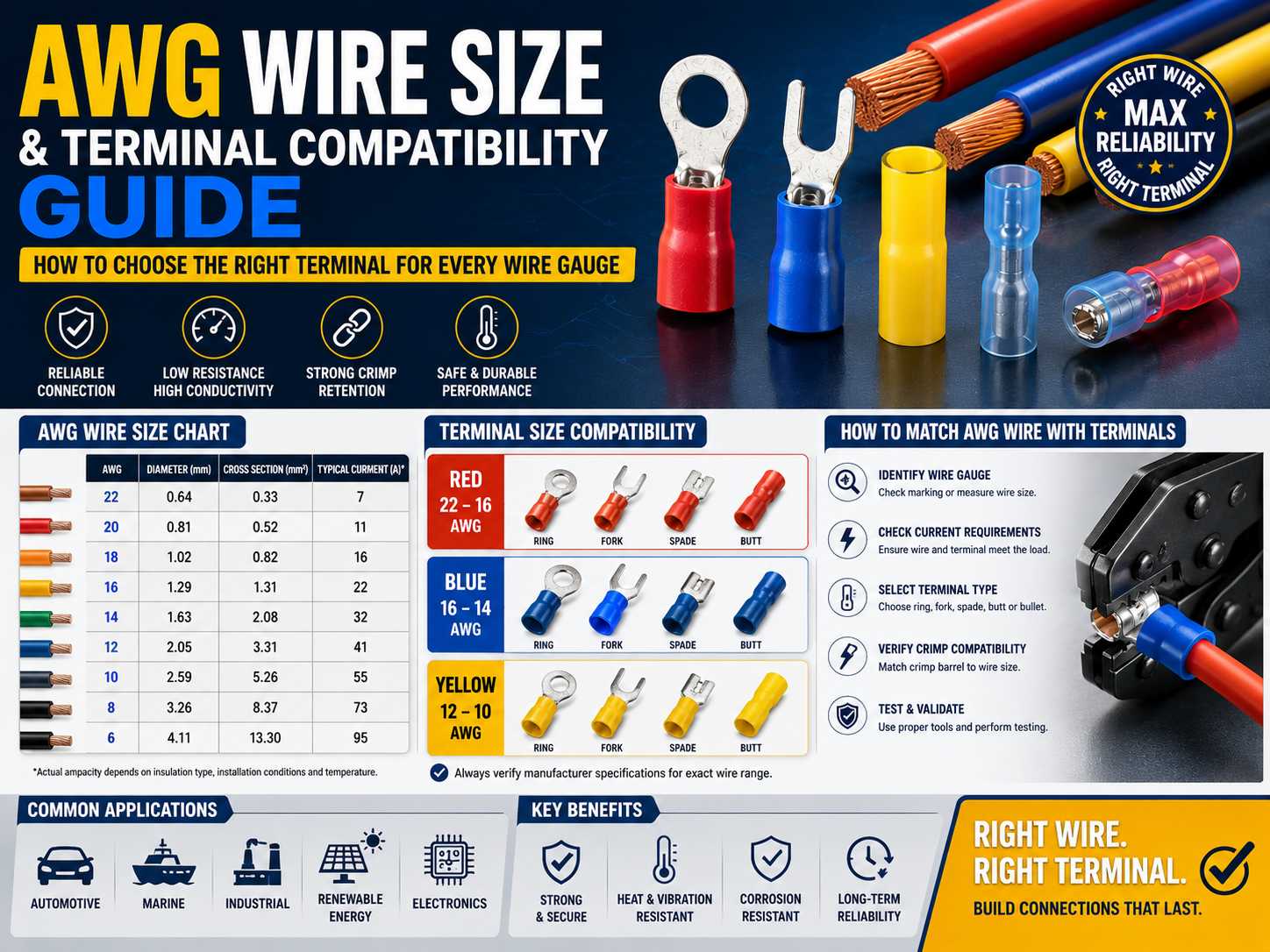
Selecting the correct electrical terminal for a specific wire size is one of the most important factors in creating safe, reliable, and long-lasting electrical connections. Whether in automotive wiring, industrial control systems, renewable energy installations, marine equipment, or consumer electronics, the compatibility between wire gauge and terminal size directly impacts electrical performance, mechanical strength, and overall system reliability.
Many connection failures can be traced back to improper wire-to-terminal matching. A terminal that is too large may create a loose connection, while one that is too small can damage wire strands and reduce conductivity. Understanding the relationship between AWG wire sizes and terminal compatibility helps engineers, electricians, OEM manufacturers, and procurement teams avoid costly mistakes.
This guide explains the AWG system, terminal compatibility requirements, selection methods, testing procedures, and best practices for ensuring reliable electrical connections.
What Is AWG (American Wire Gauge)?
AWG, or American Wire Gauge, is the standard measurement system used primarily in North America to define wire diameter and conductor size.
Unlike many measurement systems, AWG numbers work inversely. Smaller AWG numbers indicate larger wire diameters, while larger AWG numbers indicate smaller wires.
For example:
- 10 AWG wire is larger than 16 AWG wire
- 16 AWG wire is larger than 22 AWG wire
- 4 AWG wire is significantly larger than 12 AWG wire
As wire diameter increases, the wire can carry more current and generally exhibits lower electrical resistance.
AWG vs Metric Wire Sizes
Many international markets use square millimeters (mm²) instead of AWG. Understanding the conversion between these systems is important for global sourcing and engineering projects.
| AWG | Diameter (mm) | Cross Section (mm²) |
|---|---|---|
| 22 AWG | 0.64 | 0.33 |
| 20 AWG | 0.81 | 0.52 |
| 18 AWG | 1.02 | 0.82 |
| 16 AWG | 1.29 | 1.31 |
| 14 AWG | 1.63 | 2.08 |
| 12 AWG | 2.05 | 3.31 |
| 10 AWG | 2.59 | 5.26 |
| 8 AWG | 3.26 | 8.37 |
| 6 AWG | 4.11 | 13.30 |
Because suppliers may specify wire sizes differently, engineers should always verify both AWG and metric equivalents before selecting terminals.
Why AWG Matters in Electrical Connections
Wire size affects far more than physical dimensions.
The AWG rating influences:
- Current carrying capacity
- Voltage drop
- Heat generation
- Mechanical strength
- Flexibility
- Crimp performance
A terminal designed for 22 AWG wire will not properly secure a 10 AWG conductor. Likewise, a terminal designed for heavy-gauge wire cannot effectively crimp a much smaller conductor.
Proper wire gauge selection and terminal compatibility are essential for both electrical and mechanical performance.
Why Terminal Compatibility Is Important
Terminals are designed to accommodate specific conductor diameters and strand configurations.
The crimp barrel dimensions must match the wire size closely enough to create sufficient compression without damaging the conductor.
When compatibility is ignored, connection reliability decreases significantly.
How Terminal Size Affects Crimp Quality
A properly sized terminal provides:
- Strong mechanical retention
- Low contact resistance
- Uniform compression
- Stable conductivity
- High pull-out strength
The crimped connection should effectively become a gas-tight joint that minimizes oxidation and maintains long-term performance.
Risks of Using an Oversized Terminal
Using a terminal that is too large for the wire can create several issues:
- Loose wire retention
- Incomplete compression
- Increased resistance
- Reduced pull-out strength
- Vibration-related failures
In automotive and industrial applications, these issues often result in intermittent electrical faults.
Risks of Using an Undersized Terminal
Using a terminal that is too small can be equally problematic.
Potential consequences include:
- Wire strand damage
- Improper wire insertion
- Excessive conductor deformation
- Reduced conductivity
- Premature failure
Damaged strands reduce the effective conductor area, increasing resistance and heat generation.

AWG Wire Size and Terminal Compatibility Chart
Most insulated terminals follow standardized color coding to simplify wire size selection.
| Terminal Color | Compatible Wire Size |
|---|---|
| Red | 22–16 AWG |
| Blue | 16–14 AWG |
| Yellow | 12–10 AWG |
These color codes are commonly used for:
- Ring terminals
- Fork terminals
- Spade terminals
- Butt connectors
- Quick disconnect terminals
Always verify manufacturer specifications because compatibility ranges may vary slightly between brands.
Understanding Color-Coded Terminals
Red Terminals
Red terminals are typically designed for smaller wire sizes ranging from 22 AWG to 16 AWG.
Common applications include:
- Electronics
- Control systems
- Sensor wiring
- Signal circuits
Blue Terminals
Blue terminals generally support 16 AWG to 14 AWG conductors.
Typical applications include:
- Industrial control wiring
- Appliance manufacturing
- General-purpose electrical assemblies
Yellow Terminals
Yellow terminals accommodate larger wire sizes from 12 AWG to 10 AWG.
These terminals are frequently used in:
- Automotive power circuits
- Battery connections
- Industrial equipment
- Renewable energy systems
How to Match AWG Wire with Electrical Terminals
A systematic selection process helps prevent compatibility issues.
Step 1 – Identify the Wire Gauge
Wire gauge can be determined through:
- Cable markings
- Technical datasheets
- Wire gauge measuring tools
- Manufacturer documentation
Never estimate wire size visually.
Step 2 – Determine Electrical Load Requirements
Electrical load requirements influence both wire and terminal selection.
Consider:
- Operating current
- Peak current
- Voltage level
- Duty cycle
- Safety factors
Applications with continuous high current require larger conductors and appropriately rated terminals.
Step 3 – Select the Correct Terminal Type
Different applications require different terminal designs.
Common options include:
Ring Terminals
Ideal for secure bolted connections.
Common in:
- Battery systems
- Grounding applications
- Industrial panels
Spade Terminals
Support quick-connect applications and rapid assembly.
Butt Connectors
Used for wire splicing and repairs.
Bullet Connectors
Popular in automotive and detachable wiring systems.
Step 4 – Verify Crimp Barrel Compatibility
The crimp barrel must accommodate the wire diameter properly.
Verify:
- Wire insertion depth
- Barrel dimensions
- Recommended crimp tooling
- Manufacturer specifications
Even slight dimensional mismatches can affect connection quality.
Step 5 – Perform Validation Testing
Before mass production, verify compatibility through testing.
Recommended tests include:
- Pull-out force testing
- Contact resistance testing
- Visual inspection
- Crimp cross-section analysis
Validation reduces field failures and warranty claims.
Current Capacity and AWG Relationship
Wire size directly affects current carrying capacity, often referred to as ampacity.
A simplified reference chart is shown below:
| AWG | Typical Current Capacity* |
|---|---|
| 22 AWG | 7 A |
| 20 AWG | 11 A |
| 18 AWG | 16 A |
| 16 AWG | 22 A |
| 14 AWG | 32 A |
| 12 AWG | 41 A |
| 10 AWG | 55 A |
*Actual ampacity depends on insulation type, installation conditions, ambient temperature, and applicable standards.
Why Ampacity Affects Terminal Selection
As current increases, heat generation at the connection point becomes more critical.
Terminals must be able to:
- Carry the required current
- Dissipate heat effectively
- Maintain low contact resistance
- Resist thermal degradation
Underrated terminals can overheat and fail even when the wire size appears adequate.
Common AWG and Terminal Selection Mistakes
Despite the availability of standards and charts, several mistakes occur frequently.
Using Oversized Terminals
Oversized terminals often create weak crimps and poor mechanical retention.
Using Undersized Terminals
Undersized terminals can damage conductors and reduce electrical performance.
Ignoring Current Requirements
Wire size alone does not guarantee adequate performance.
The terminal must also support the required electrical load.
Ignoring Environmental Conditions
Environmental factors such as:
- Moisture
- Corrosion
- Vibration
- Temperature fluctuations
must be considered during selection.
For harsh environments, waterproof heat shrink terminals may be preferable.
Using Incorrect Crimping Tools
Improper crimping tools frequently cause connection failures.
Common problems include:
- Under-crimping
- Over-crimping
- Wire strand damage
- Inconsistent compression
Always use tooling recommended by the terminal manufacturer.
Choosing Terminals for Different Applications
Automotive Wiring
Automotive environments require:
- Vibration resistance
- Corrosion protection
- Temperature durability
Heat shrink terminals and tinned copper terminals are commonly used.
Marine Applications
Marine environments involve constant moisture and salt exposure.
Recommended solutions include:
- Waterproof terminals
- Heat shrink connectors
- Corrosion-resistant plating
Industrial Control Panels
Industrial control systems often utilize:
- Ring terminals
- Fork terminals
- Insulated crimp terminals
These provide secure and serviceable connections.
Renewable Energy Systems
Solar and energy storage applications require terminals with:
- UV resistance
- Corrosion resistance
- High current capacity
Consumer Electronics
Smaller wire gauges are common in electronic devices.
Compact terminals with precise crimp dimensions are typically preferred.
Material and Plating Considerations
Wire size compatibility is only one part of terminal selection.
Material and plating also influence performance.
Common Terminal Materials
Copper offers excellent conductivity.
Brass provides a balance between conductivity and strength.
Phosphor bronze delivers superior elasticity and fatigue resistance.
Common Plating Options
Tin plating is widely used for general electrical applications.
Nickel plating improves wear resistance and temperature performance.
Gold plating provides exceptional corrosion resistance and signal reliability.
Silver plating offers excellent conductivity for high-current applications.
Selecting the appropriate plating helps maximize terminal lifespan.
Testing Methods to Verify Compatibility
Manufacturers use various testing methods to ensure wire and terminal compatibility.
Pull-Out Force Testing
Measures mechanical retention strength.
Crimp Cross-Section Analysis
Evaluates crimp compression quality and conductor deformation.
Contact Resistance Testing
Measures electrical efficiency at the connection point.
Temperature Rise Testing
Verifies performance under electrical load.
Vibration Testing
Simulates real-world operating conditions in automotive and industrial environments.
Industry Standards Related to AWG and Terminal Selection
Several organizations provide guidance and testing requirements for electrical connections.
Important standards include:
- UL
- IEC
- ISO
Compliance helps ensure safety, consistency, and market acceptance.
How Manufacturers Ensure Proper AWG Compatibility
Reliable terminal manufacturers implement multiple quality control measures.
These often include:
- Design validation
- Material inspection
- Crimp testing
- Automated optical inspection
- Dimensional verification
- Traceability systems
Manufacturers with strong engineering support can also provide guidance on wire-to-terminal matching for specific applications.
Future Trends in Wire and Terminal Technology
As electrical systems become more advanced, terminal technology continues evolving.
Key trends include:
- High-voltage EV systems
- Miniaturized electronics
- Automated crimp monitoring
- Smart manufacturing processes
- Advanced corrosion-resistant materials
Future terminal designs will increasingly focus on reliability, efficiency, and automated quality assurance.
Conclusion
Proper AWG wire size and terminal compatibility are fundamental to creating reliable electrical connections. Selecting the correct terminal for a specific wire gauge improves conductivity, mechanical retention, safety, and long-term performance.
Successful terminal selection requires evaluating:
- Wire gauge
- Current requirements
- Terminal type
- Crimp barrel dimensions
- Material selection
- Environmental conditions
- Testing and validation requirements
By following established compatibility guidelines and working with experienced terminal manufacturers, engineers and buyers can significantly reduce connection failures and improve overall system reliability.
FAQ
What does AWG mean in electrical wiring?
AWG stands for American Wire Gauge, a standardized system used to measure wire diameter and conductor size.
What terminal color corresponds to which AWG range?
Generally:
- Red: 22–16 AWG
- Blue: 16–14 AWG
- Yellow: 12–10 AWG
What happens if I use the wrong terminal size?
Incorrect terminal sizing can cause loose connections, damaged wire strands, overheating, increased resistance, and premature failure.
Can one terminal size fit multiple wire gauges?
Yes. Most terminals are designed to accommodate a range of wire sizes, but the wire must remain within the manufacturer’s specified range.
Why is pull-out testing important?
Pull-out testing verifies the mechanical strength of the crimped connection and helps ensure long-term reliability.
Are heat shrink terminals available for all AWG sizes?
Yes. Heat shrink terminals are available in a wide range of AWG sizes, from small signal wires to large power conductors.
What is the difference between AWG and mm² wire sizing?
AWG measures wire diameter using a gauge system, while mm² measures conductor cross-sectional area directly.
Which terminal type is best for automotive wiring?
Heat shrink terminals, ring terminals, and vibration-resistant crimp terminals are commonly recommended for automotive applications due to their durability and environmental protection.

